Induction Motor Slot Pole Combinations

The comparison of electromechanical characteristics of a 4-pole and a 6-pole induction motor with 36 stator slots in combination with 28, 33, 34, 44 and 46 rotor slots is presented. The comparison of electromechanical characteristics of a 4-pole and a 6-pole induction motor with 36 stator slots in combination with 28, 33, 34, 44 and 46 rotor slots is presented. A comparative analysis is performed by evaluating: the iron losses a. Determination Of Rotor Slot Number Of An Induction Motor. 229 2 Information Content of the Search Coil Voltage It is well known that, for a P pole pair, induction motor with Z number of rotor slots, rotating at a mechanical frequency fr; the harmonic frequency of the flux observed on the stator reference frame is frsh and is given by (1) 1. Modulation motor is the world’s most innovative AC induction motor.Although it is basically a single-winding, two-speed squirrel cage motor, the PAM motor features one outstanding characteristic that makes it versatile in application and efficient in operation, especially where less than peak load operation is desired: the PAM motor does not.
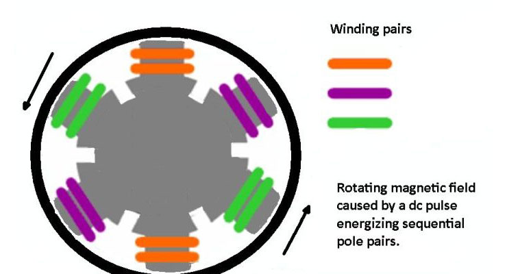
There are many much more interesting questions related to the pole number of induction motors, e.g.:
1. Does the induction motor supplied by the main grid (say, 50 Hz) increases its torque capability in 'p' times with growing pole number 'p' since its speed decreases in 'p' time (like in a gearbox)?
2. Let's we have an induction motor with p=2 and feed it from 50 Hz grid. Then we re-connect the winding coils to arrange p=4 and feed if grow 100 Hz grid. Are performances of these two motors different or the same? Please note excluding frequency and inter-coil connections all remained the same.
It depends on the required speed. n (rpm) = (60 x f) / N where:- f = frequency and N = number of pole pairs. The 60 is there to convert from revolutions per second to revolutions per minute as the frequency is in cycles per second. Pole pairs is there because that any pole must be constructed in a pairs top and bottom / left right, so with one cycle it will move half the distance.
If you are using 50Hz and have a two pole motor 60 x 50 / 1 = 3000 rpm. The induction motor will run at a slight less speed due to 'slip' which is what gives the motor its torque. For example 5.5kW, 400v, 2 pole motor will run at approximately 2880 rpm.
For a four pole machine, 60 x 50 / 2 = 1500 rpm so the same size motor at 5.5kW, 400v but 4 poles will have a nominal speed of 1500rpm but will run near 1455 rpm.
When selecting a three phase motor, the number of poles is chosen to achieve the speed of rotation that you require. Here are two tables, one for a 50 Hz power supply and one for a 60 Hz power supply:
The formula is n = 60 x f /p where n = synchronous speed; f = supply frequency & p = pairs of poles per phase. The actual running speed is the synchronous speed minus the slip speed.
For a 50 Hz three phase supply:

2 poles or 1 pair of poles = 3,000 RPM (minus the slip speed = about 2,750 RPM or 6 -7% n)
4 poles or 2 pairs of poles = 1,500 RPM
6 poles or 3 pairs of poles = 1,000 RPM
8 poles or 4 pairs of poles = 750 RPM
10 poles or 5 pairs of poles = 600 RPM
12 poles or 6 pairs of poles = 500 RPM
16 poles or 8 pairs of poles = 375 RPM
For a 60 Hz three phase supply:
2 poles or 1 pair of poles = 3,600 RPM (minus the slip speed = about 2,750 RPM or 6 -7% n)
4 poles or 2 pairs of poles = 1,800 RPM
6 poles or 3 pairs of poles = 1,200 RPM
8 poles or 4 pairs of poles = 900 RPM
10 poles or 5 pairs of poles = 720 RPM
12 poles or 6 pairs of poles = 600 RPM
16 poles or 8 pairs of poles = 450 RPM
To determine the number of poles, you can read the data plate directly or calculate it from the RPM stated on the data plate or you can count the coils and divide by 3 (poles per phase) or by 6 (pairs of poles per phase). Where the power of the induction motor is constant, the torque increases at the rate that the speed decreases.
With the advent of variable frequency drive (VFD), you can have any frequency / rated volts you desire. I often see name plates with things like 575VAC, 42.5 Hz etc. When these 'specials' are made I usually see 6 pole machines - but that may be just a manufacturer's preference.
Space harmonics fluxes are produced by the windings, slotting, magnetic saturation, inequalities in the air gap length. These harmonic fluxes induce voltages and circulate harmonic currents in the rotor windings. The interaction between the harmonic currents generated in the rotor and the harmonic fluxes results in the Harmonic torques, vibrations and the noise.

The air gap flux set up by the three phase stator windings carrying sinusoidal currents. The wave shape is non-sinusoidal in nature. According to Fourier series analysis, any non-sinusoidal flux is equivalent to the combination of a number of sinusoidal fluxes of fundamental and higher order harmonics. Since, the flux wave shape has half-wave symmetry, all even harmonics (2,4,6 ……) are absent in Fourier series.
A non-sinusoidal flux can be resolved into fluxes of fundamental and higher order odd harmonics (3, 5, 7, 11, 13, etc). The third harmonic flux wave produced by each of the three phases neutralizes one another. The resultant air gap flux is free from third harmonics and its multiples. This is because the third harmonics in the flux wave of all the three phases are in space phase, but differ in time phase by 120 degrees.
Harmonics Induction Torques
A 3 phase winding carrying a sinusoidal currents produces space harmonics of the order h = 6k ± 1, where k is a positive integer (1, 2, 3…..). The synchronous speed of the hth harmonic is (1/h) times the speed of the fundamental wave. Space harmonic waves rotate in the same direction as the fundamental wave, if h = 6k + 1 and if h = 6k – 1 than it rotates in the opposite direction.

Space harmonic wave of the order h, is equivalent to a machine with the number of poles equal to (h x number of poles of the stator). Therefore, the synchronous speed of the hth space harmonic wave is
Where,
Induction Motor Slot Pole Combinations Generator
- f = supply frequency
- P = number of poles of the stator
Thus, for the value of k = 1, a 3 phase winding will produce backward rotating fifth harmonic at the speed of (1/5) of the synchronous speed and forward rotating seventh harmonic rotating at a speed of (1/7) of the synchronous speed. These harmonics alone will have an effect on the operation of the motor.
The speed torque characteristics of the fundamental flux and the fifth and seventh space harmonic flux are shown below.
The fifth harmonic torque opposes the fundamental component torque as the fifth harmonic flux rotates in the opposite to the rotation of the rotor. Thus, the fifth harmonic flux produces a braking torque. The seventh harmonic flux rotates in the same direction as that of the fundamental flux. Hence, the resultant torque speed characteristic will be the combination of the fundamental fifth and seventh harmonic characteristic.

The resultant torque speed characteristics have two dips, one near (1/5) of the synchronous speed and the other near (1/7) of the synchronous speed. The dip near (1/5) of the synchronous speed occurs in the negative direction of the motor rotation.
The motor will accelerate to the point L, which is the interaction between the load torque characteristic and the motor torque-speed curve. This motor torque is developed because of the fundamental flux alone. The load torque curve intersects the motor torque speed characteristics at the point A this is because of the presence of the seventh harmonics flux torque.The seventh harmonic flux torque curve has a negative slope at the point A.
The motor torque falls below the load torque. At this stage, the motor will not accelerate up to its normal speed, but will remain running at a speed which is nearly (1/7) of its normal speed, and the operating point is A. This tendency of the motor to run at a stable speed as low as one seventh of the normal speed Ns. In this condition the motor is unable to pick up its normal speed is known as crawling of the motor.
Induction Motor Slot Pole Combinations List
Crawling can be reduced by reducing fifth and seventh harmonics. This can be done by using a chorded or short pitched winding.